PROJECTS
Latest Projects

Custom Glasses Cases
Introduction
The project is designing custom glasses cases personalized to any pair of glasses available. These cases will be designed, measured and started printing within an hour. For the project, the lead engineer will be taking advantage of the school's 3-D printer to produce these custom cases, along with excel and solid works.
There is a need for a glasses case that is not big and bulky so this will also factor into my design.
Many pairs of glasses don’t come with a case. The goal of this project is to produce custom, cheap glasses cases for any pair of glasses. This will be a smaller design than most glasses cases used today, and will be able to be transported in a pocket. Most cases on sale are one sided built for safety or size, not both. This case will be small, lightweight and strong enough for every day functions.
Requirements
For the glasses cases to be successful they must maintain the following requirements:
The custom case must be measured, designed and given to the customer within one hour.
The design of the glasses is to be within 1/4" longer and wider than the glasses are all around. The glasses case 1/4" is designed around the inside fit and the thickness. This ensures the glasses cases are small as possible.
The case must not bend .1 inches under a twenty pound load.
The case must open with a 6 pound force.
The case must stay closed until opened purposely.
Equations
The equations used come from statics. Bending stress equations can see how thick the case will need to be along with the deflection due to a force. The equation for moment of inertia for a hollow pipe was used. It models the top of my case perfectly; the equation is I= π/4(r2^4-r1^4). For bending stress, the equation Vmax= -PL^3/48EI was used, E being the modulus of elasticity and I being the moment of Inertia. The top of the glasses case has been evaluated as a beam with a given length, height and thickness to determine the deflection. The case was then modeled in solid works with these calculated values.
Design Evolution
The project started out as drawn ideas for case designs. There were a few different shape ideas. What created the shape used now is the close fit between the case and the glasses inside the case. The case does not leave more than a .25 inch gap from the case to the glasses on the inside. This is to make sure the case is as small as possible and also for the glasses to have little room to shake inside the case. The design is to have the glasses fit securely in the case.
The case also could have been opened in many ways. The original drawing had the case opening from the top. The case could have had a snapping cap that would fit to the case at the top of the body. However I am not aware of the tolerances of the 3-D printer on campus so I decided to go with a different design. This would have been a risk because if the lid would not stay on the case I would have to redesign the case or print new caps. I decided to go with a case that split down the middle, more like traditional hard cases.
The first design was a flat case and is shown in figure 4. It had sharp edges and had a clasp that needed force to open. This design also had a pin going through the case keeping the top and bottom parts together. The design looked clunky and was a rough prototype.
First Design
This was my second design. It has filets and has an arched top to better fit the natural curve of glasses. My final design took the flat surface on the bottom away, and is almost a mirror of the top part of the case. It is shown in figure 5.
Analysis
Analysis began with creating the solid works model of the case. The dimensions changed when choosing a thickness and making sure the glasses fit in the case. Using the equation Vmax= -PL^3/48EI, different thicknesses were tested for deformation in the centroid of the top part of the case. This area is the widest and longest part of the case making it the most susceptible to bending. The values of length and width could not be changed very much so the value tinkered with is the desired thickness. The findings were for any deformation of less than .01 inch, the thickness needed to be .1 inches. This thickness can hold up to a 20 lb-force (89 Newtons). The calculations page is found in Appendix-A.
Finite element analysis was done on my solid works model. The case deflected .00618 millimeters, which is .000243 inches. This is close to my calculated values of deflection of .000389 inches under a 5 pound force. In both instances the calculations were done on the top part of the case, not the whole assembly. In solid works, the fixture was the bottom ring of the case, acting as it were closed or set on the ground. The 5 pound force, or 89Newton, was applied over the surface area of the top of the case.
Analysis was also done finding how much force it takes to open the case. It was evaluated as a force fit. The psi holding the case together was found to be 1.9 Psi. The surface area, between the top and bottom parts on the case, in contact was 3.02 inches^2. The Force needed to open the case came out to 5.85 pounds.
Construction
The project will be designed in solid works and made with Central Washington Universities' 3-D printer located in the Hogue lab. An excel spreadsheet will be made to simplify changing dimensions in the already made solid works model. This ensures the custom case is made quickly to standards pre-determined. The engineer will be able to take any pair of glasses and quickly measure and apply the dimensions to solid works, making a new custom solid works model based on the new dimensions. This model will then be printed and given to the customer within minutes, not days. The material used in the printer is abs, a hard plastic. The part may need some touching up, or deburing depending on the quality of the 3-D printer.
A dial caliper will be used to quickly measure the desired dimensions. This will help the process stay under one hour. The excel spreadsheet will have dimensions like length, height, but also formulas that can change the thickness of the case if need be. This spreadsheet will simplify all aspects of design and calculations. The excel spreadsheet will be able to calculated the needed thickness for the new glasses along with changing the desired dimensions of the new custom case.
Testing
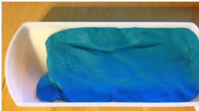
The first test done was testing the requirement of open space in the case when the glasses are inside. My requirement was for .25 inches or less between the cases walls. This was meant to keep the design of the case tight to the glasses. In the X direction the case is out of tolerance. It is measured at about and .7 inch gap. The Y direction is perfect and is less than the .1 inch margin. Measuring the Z direction( up and down) took some imagination. The top part of the case was filled with modeling clay and then the cases were closed with the glasses inside. The mark made in the left picture shows were the glasses are touching and the leftover clay between the mark and the case show how much available space is left when the case is closed. this was measued with the depth part of a dial caliper to be about .14 inches.
Another test done was testing the Vmax or deflection under certain loads. The case was designed not to bend certain amounts under certain loads. The requirement is for the case to not bend .1 inch under 10 pounds. The test was done using a 25 pound dumbbell placed on top of the case. To simulate a point load, a dime was placed between the case and weight. Modeling clay was placed in the case making a mold of the case. The mold was measured and then placed back in the case. The weight was then placed on the case. Taking the modeling clay out and re-measuring showed how much the case bent during the test. This difference in height was the deflection the case experienced. I got values between .02 and .03 inches. This will compared to calculated data.
Another test done was testing the force it takes to open the case. The requirement was to open the case with a 6 pound force. The case should not be over this amount or it would be too hard to open and would not satisfy my requirements. The way the test was conducted took some imagination. Two holes were drilled into the top of the glasses case. Then a fish weighing scale is hooked threw the holes and is used to measure the weight it takes to separate the top and bottom of the case.
My last test was timing how long it took to measure and make a new model in solidworks. Using excel within solidworks it took 14 minutes to change my model. Just changing the individual parts took 17 minutes. Both under an hour and almost negligible when considering printing takes 8 hours.
Budget
The original estimating cost my project to be 60 dollars. Upon gathering more information about testing and the amount of material needed to produce a single case, more will be necessary. More than one case will be made so this will increase the amount of money needed for the project. One case will be made to show my teachers and two more will be made for testing data. After doing the solid works model I found the volume to be more than 4 cubic inches for my first case. The total for this case is 26.58 dollars. There is no external source funding the project. The cost for each case is measured by the cubic inches of the case. The price is 6 dollars per cubic inch.
Resources
The lead Engineering student is responsible for the completion of this project. Teachers Dr. Craig Johnson, Mr. Charles Pringle, Mr. Roger Beardsley and Mr. Darryl Fuhrman have aided in the completion of this project.


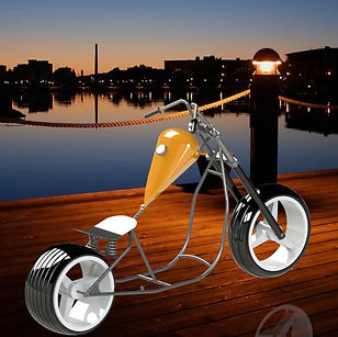
Bobber style Motorcycle
This is a project i created in solidworks. I designed and made everything you see in this picture. I am certified solidworks user in washington state.